Rocket engine test stand
overview
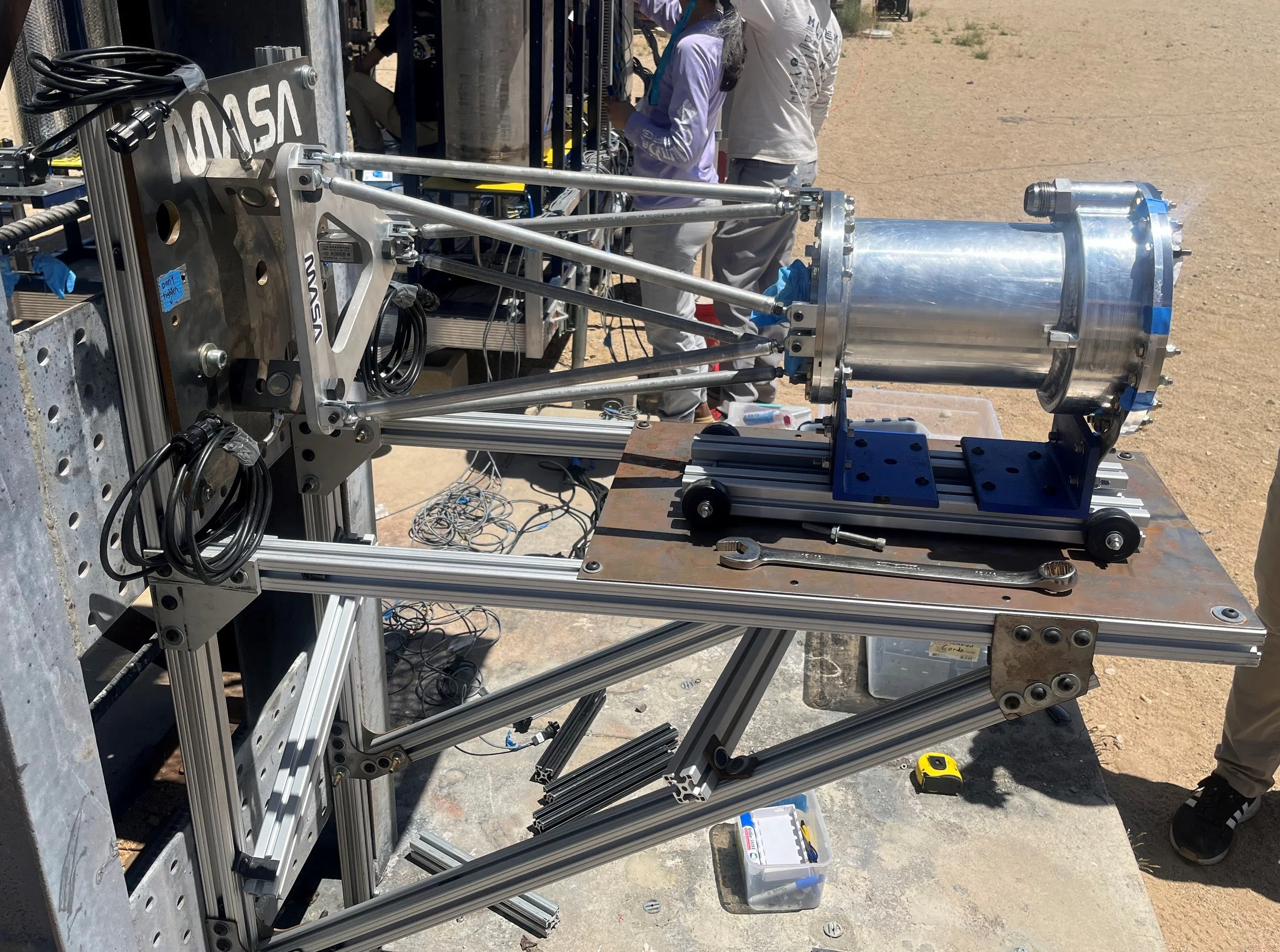
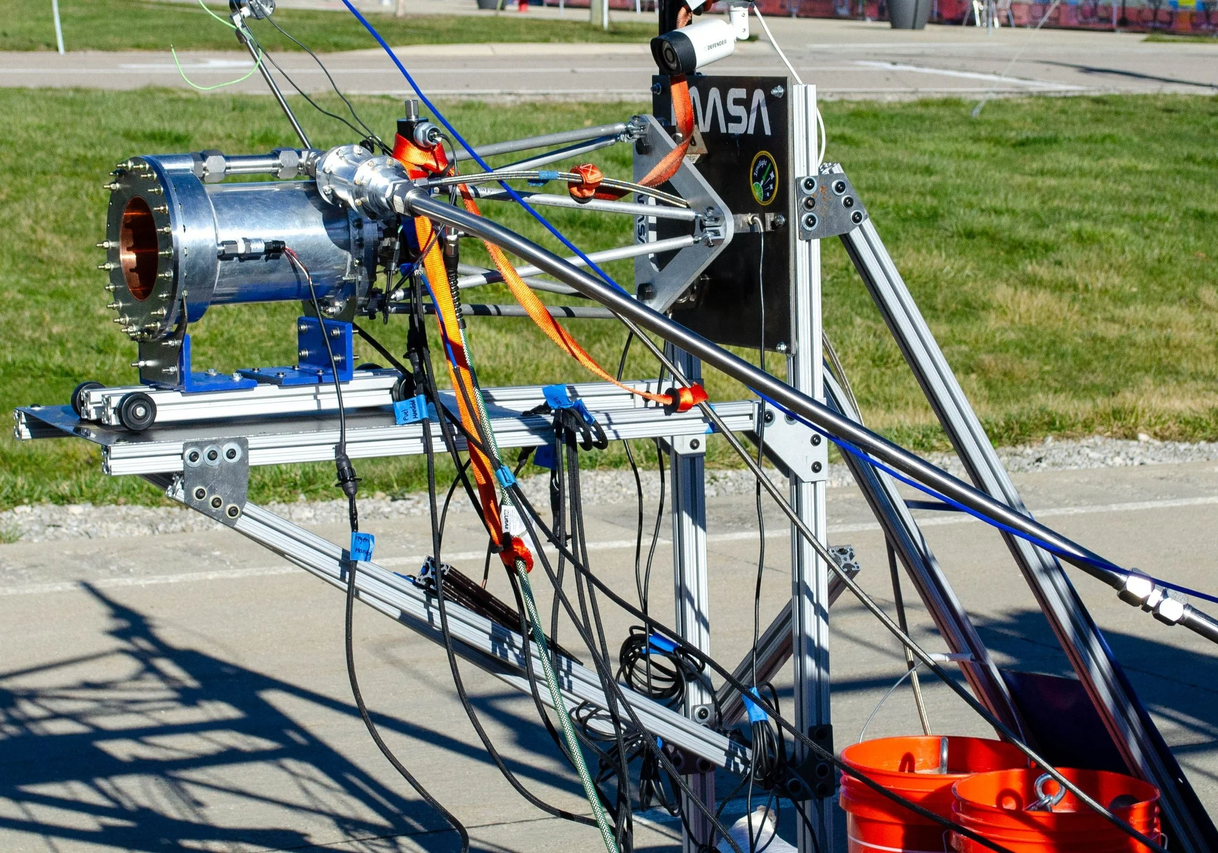
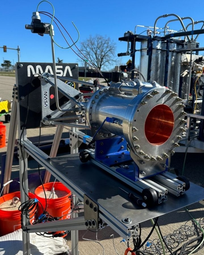
The Engine Stand was a structure for supporting and measuring the thrust of a 2800 lbf kerolox rocket engine during a full duration hotfire test. It featured a Thrust Transfer Structure (TTS) consisting of adjustable-length aluminum rods that secure the engine to a loading plate by locking all six degrees of freedom, while also allowing for flexibility in assembly tolerances and accessibility for engine plumbing.
Hotfire Configuration
coldflow Configuration
my role
As part of the UM rocketry team MASA, I was the Responsible Engineer (RE) for the Engine Stand used in the 2024 coldflow and hotfire testing campaigns for a kerolox rocket engine.
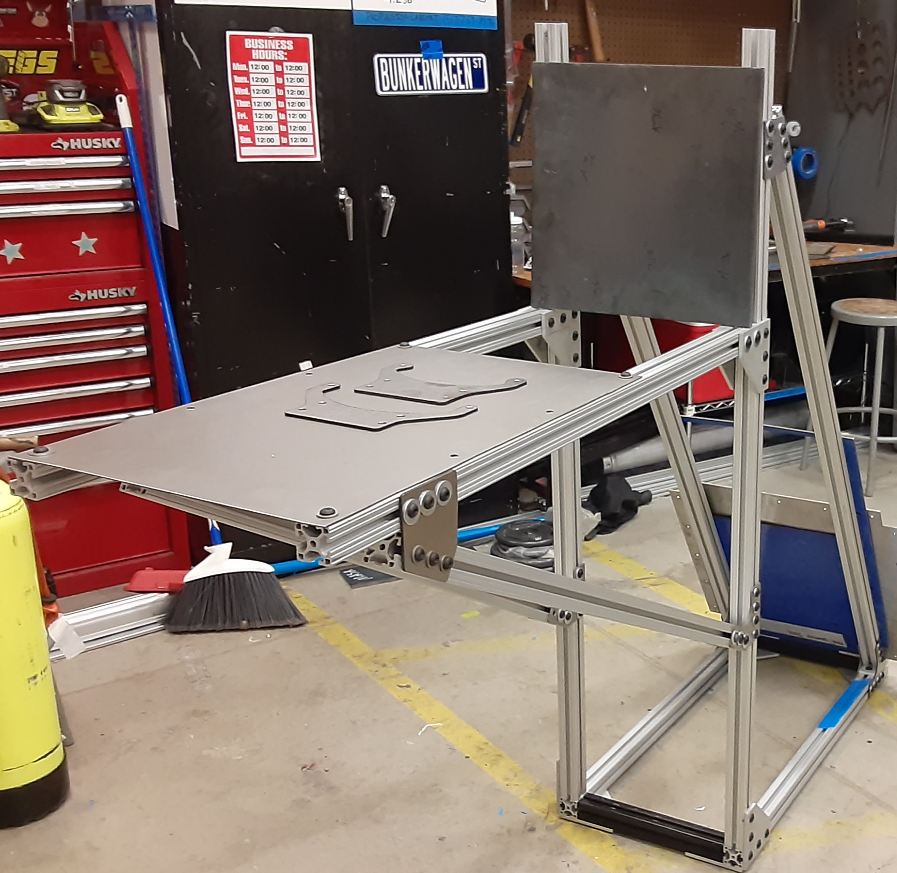
Assembled stand frame from 80/20.
Manufactured the support plate and gussets using vertical bandsaw, hole punch, and hand tools.
Sole RE for transport, on-site assembly, and system integration with the engine and static structure at the Mojave Test Area in California.
outcome
The Engine Stand succeeded in satisfying the system requirements:
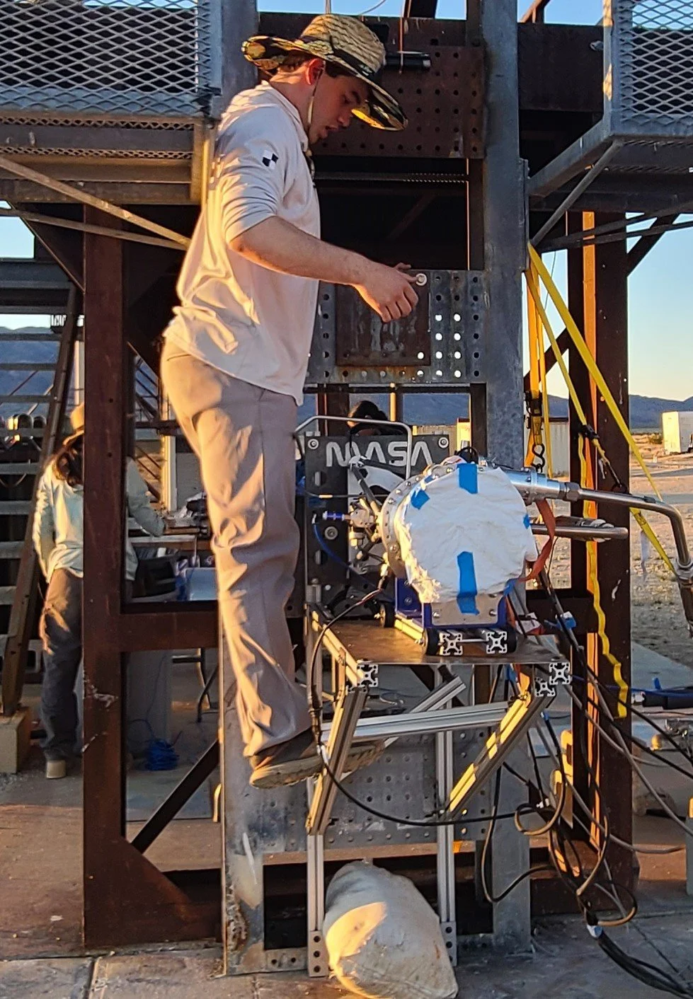
TTS successfully tested to 1.25x the expected maximum engine thrust for the full 20 sec engine burn duration (shown bottom-right).
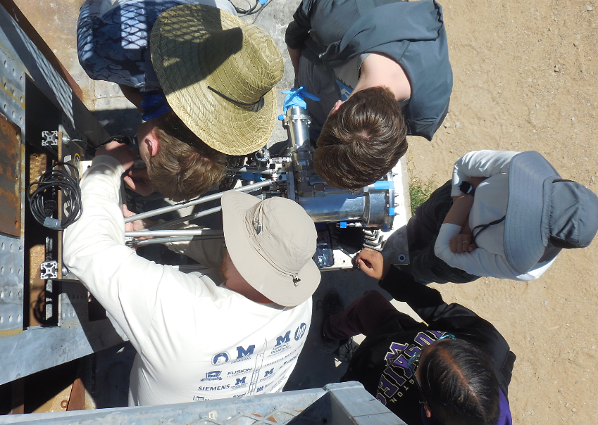
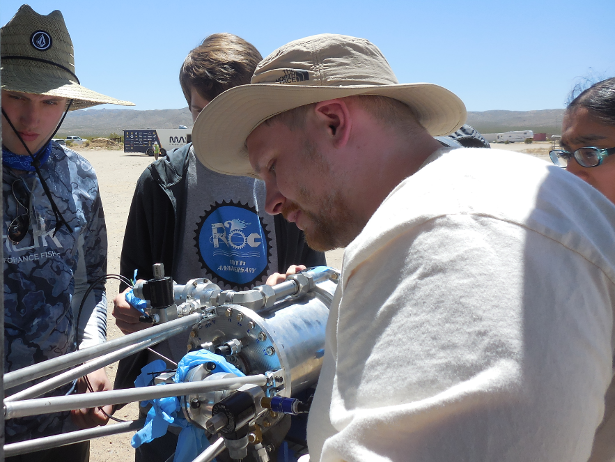
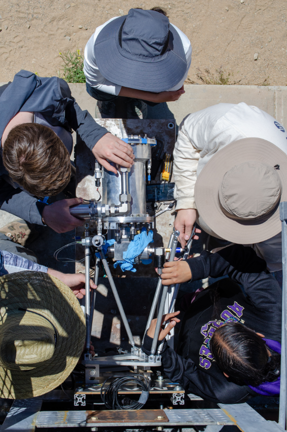
Engine plumbing readily accessible and was successfully routed for both coldflow and hotfire tests (shown bottom-center).
Stand-TTS-Engine alignment was sufficient for uniform uniaxial thrust transference from engine to load cells.
Stand easily modified for integration with on-site structure.
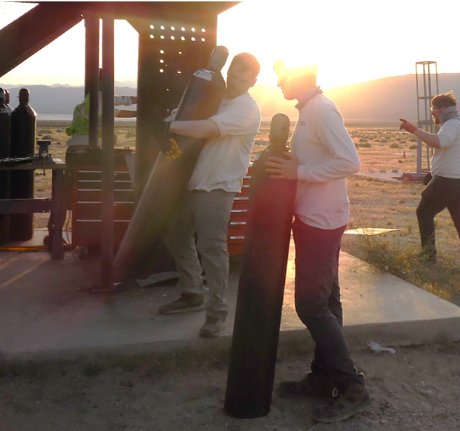
Demonstrated reasonable structural stability in the presence of unforeseen loading conditions (shown bottom-right).
completed engine plumbing
compression test
(3500 lbf)
informal weight test
top skills utilized
manufacturing
structural analysis
High pressure system testing
cryogenic system testing
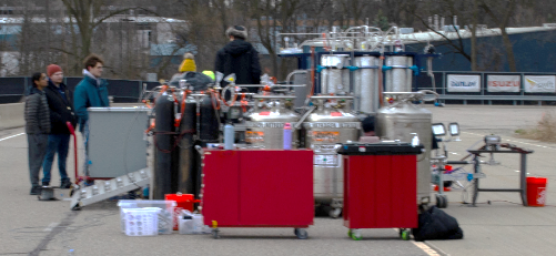
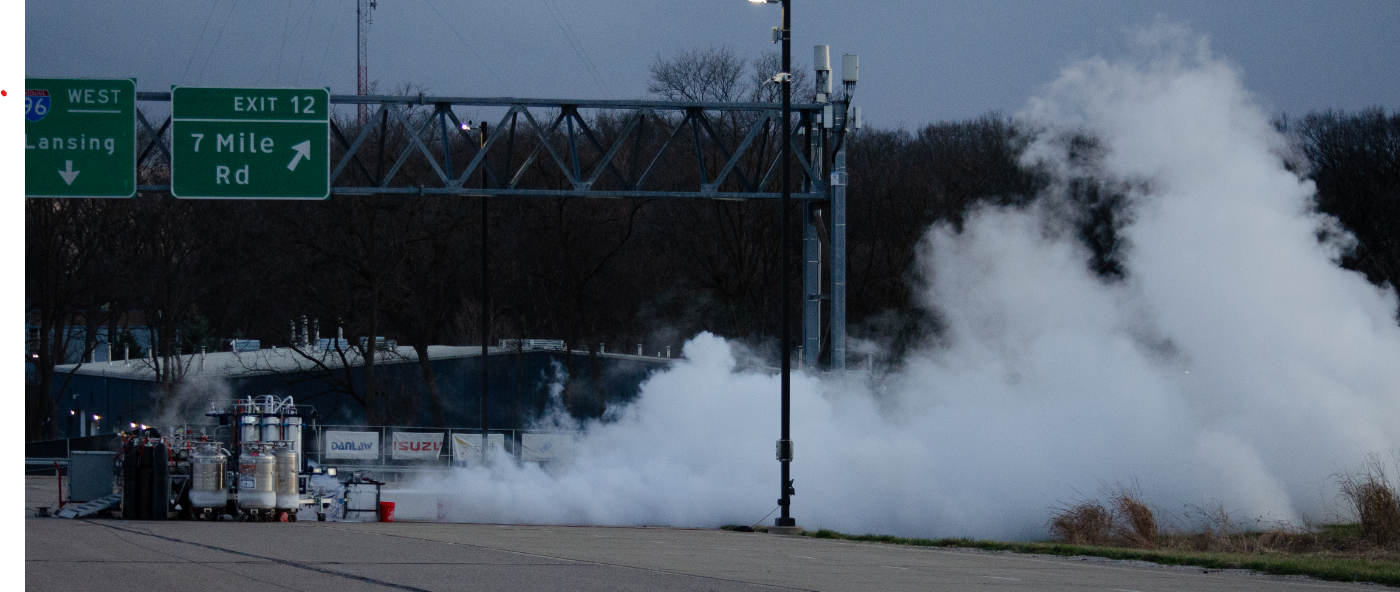
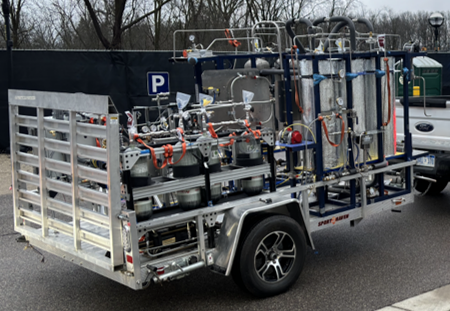
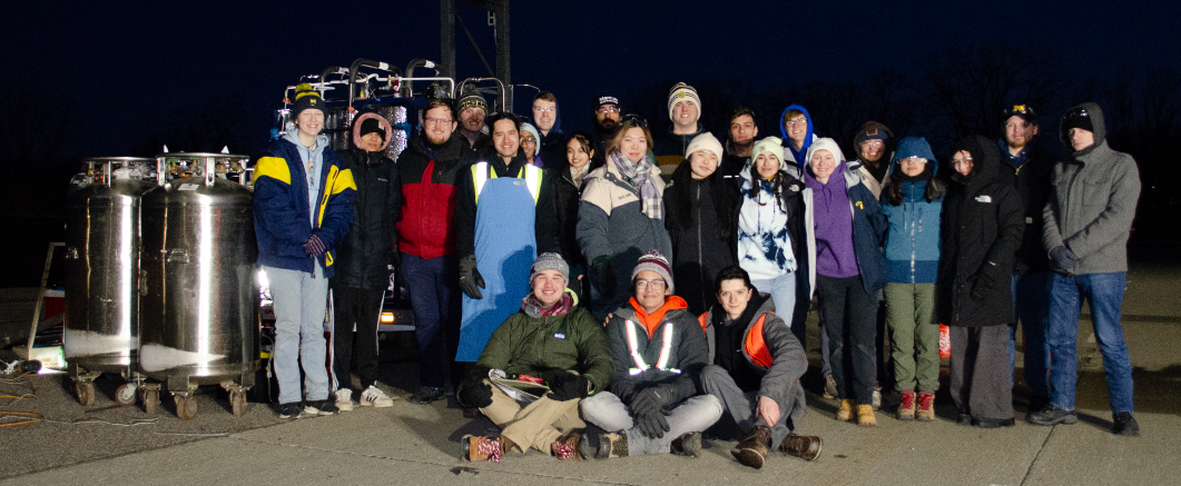
winter 2024 coldflow testing campaign


summer 2024 hotfire testing campaign





technical details
high level overview
In the Summer of 2023, UM’s student rocketry team MASA initiated a two-year design cycle for the single-stage sounding rocket Limelight. The propulsion system is the regeneratively cooled pressure-fed liquid bipropellant (RP-1/LOX) engine ME-5. The timeline from the initial design phase through the engine hot fire test was as follows:
Winter-Summer 2023: Engine and GSE (Ground Station Equipment) system design and component testing
Fall 2023: Fabrication and component testing
Winter 2024: Fabrication and full-scale system cold flow testing campaign
Summer 2024: Full-scale system hot fire testing campaign
The ME-5 cold flow and hot fire testing campaign tested system integration of various custom components contributed by several subteams, including (non-exhaustive):
Bang-Bang Tank Pressure Control (BBTPC)
Pintle injector
Fuel and LOX valves
Regeneratively-cooled combustion chamber
Nozzle
Synnax (data acquisition and hardware control framework fully developed in-house)
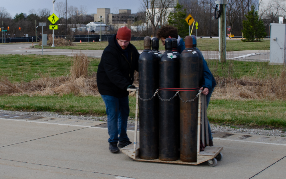
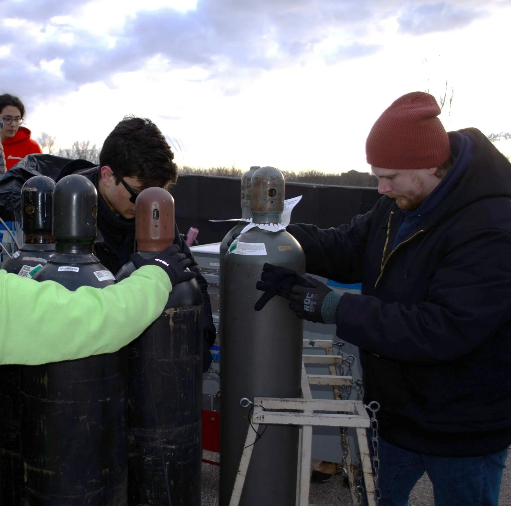
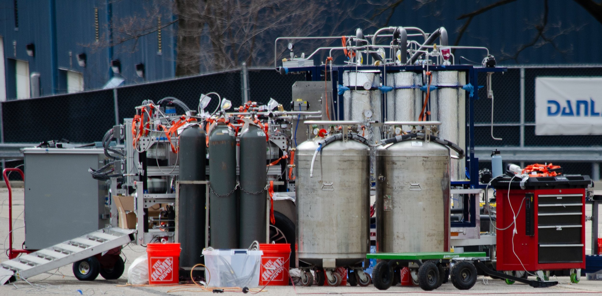
Cold flow testing was completed at Mcity in Ann Arbor, which is sufficiently isolated to contain the safety radius necessary for system testing at operational pressures (~3700 psi) with inert substitutes (i.e. water in place of RP-1 and liquid nitrogen in place of liquid oxygen). Hot fire testing was completed at the Reaction Research Society (RRS) in California, which is equipped with the facilities necessary for full-duration engine testing with RP-1 and LOX.
my role
Since joining the project in July 2023, I’ve made the following contributions (in chronological order):
BBTPC hardware
Hardware design and fabrication
Material sourcing and maintenance of engineering BOM
GSE system integration
Testing
GSE fluid system fabrication, assembly
Component manufacturing
System cold flow testing
SOP writing
Fluid system assembly
Test operations support
System hot fire testing
SOP writing
Engine test-stand fabrication
LOX cleaning of GSE fluid system
System preparation, transportation, and assembly
engine stand fabrication
engine stand:
Given past team experiences with vertical engine testing, it was decided early on that the engine will be hot fired horizontally using the static structure at RRS.
This would require building a stand beforehand with minimal knowledge of the configuration of the RRS stand.
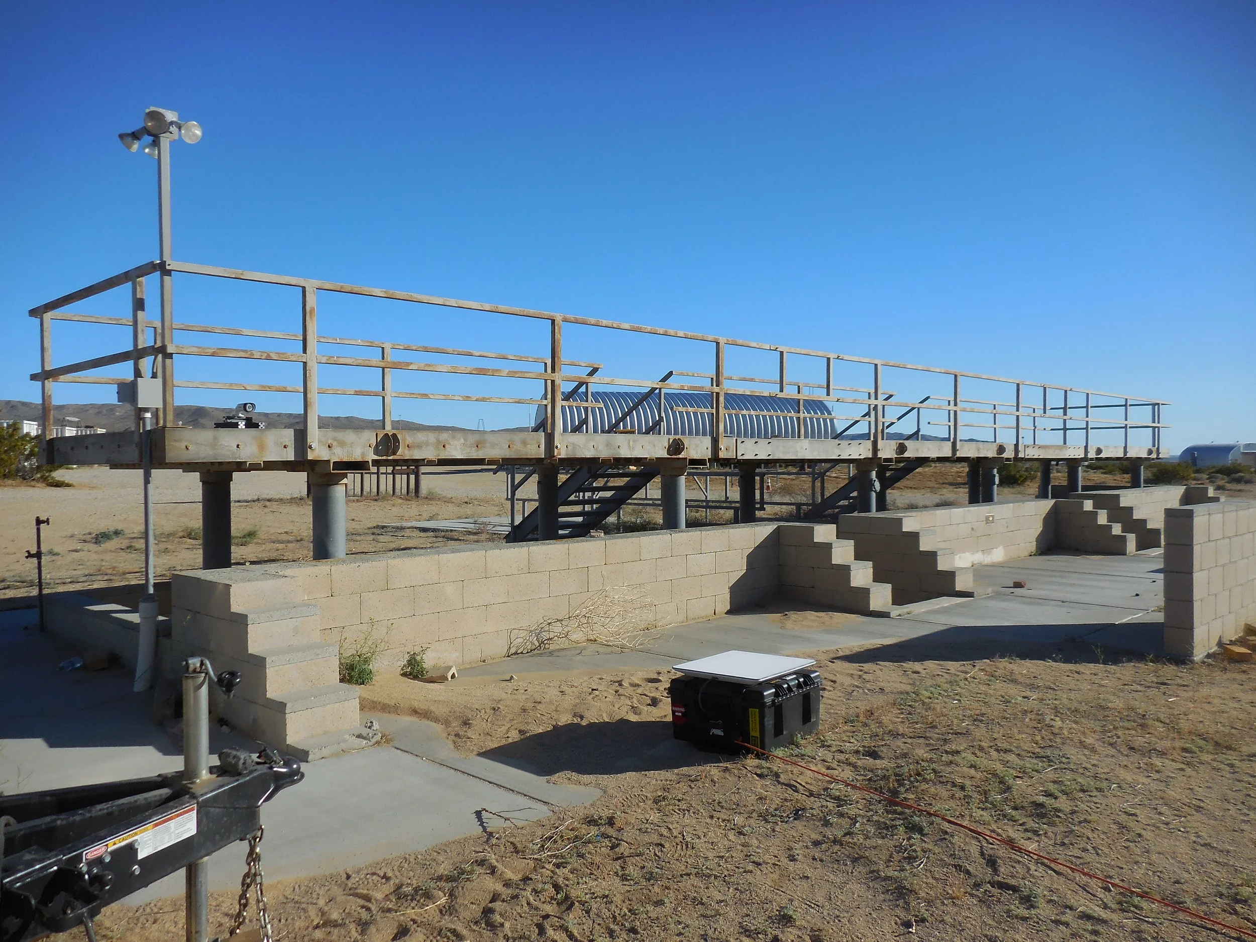
Site limitations required that the structure be able to stand independently while plumbed to our GSE during our coldflow testing campaign, while also being easily adapted to the RRS mounting structure for our hot fire testing campaign to follow.
This was achieved by building the structure shown to the left using 80/20, where the entire structure was used for the cold flow tests.
For the hot fire tests, the rear-support structure was removed to allow the stand to sit flush with the RRS structure.
The joints were then drilled through and frictional fasteners were replaced with bolts with nylon-insert locknuts to reinforce the structure against vibrational reconfiguration in transit from Michigan to California.
thrust transfer structure (TTS):
TTS is minimal weight truss with a design based off Stewart Platforms.
This allows locking of all 6 degrees of freedom, thereby preventing engine motion relative to the back-panel mount.
Each rod is connected at either end via clevis & shoulder bolts such that the structure is comprised entirely of two-force members.
This configuration is structurally efficient as it supports design loads with minimal size and weight addition.
The geometry of this configuration is also conducive to allowing engine plumbing connections.
This stand was tested before hotfire in compressive loads 1.25 x the expected thrust of the engine for 2x the expected burn duration.
engine cart:
Since the engine is being tested horizontally, a cart was needed to support the weight of the engine while allowing for elastic compressive deformation in TTS .
The cart shown to the left bolts onto either side of the engine using the two top gussets; 2 bolts into the chamber flange and 2 in the injector flange.
