Rocket Tank Pressure Control
overview
Bang-bang Tank Pressure Control (BBTPC) is a favorable solution for throttling of pressure-fed liquid rocket engines due to mechanical simplicity and inherent robustness to unsteady system dynamics. It maximizes engine efficiency by accurately maintaining optimal propellant tank pressures across a broad range of pressure drops. As part of the UM rocketry team MASA, I designed, fabricated, and tested BBTPC hardware for a kerolox rocket engine.
my role
As part of the UM rocketry team MASA, I designed, fabricated, and tested BBTPC hardware for a kerolox rocket engine. I designed a fluid manifold for cartridge valves using CAD and FEA, created engineering drawings, sourced control valves, fabricated fluid system hardware, and supported high-pressure (3700 psig) test operations.
outcome
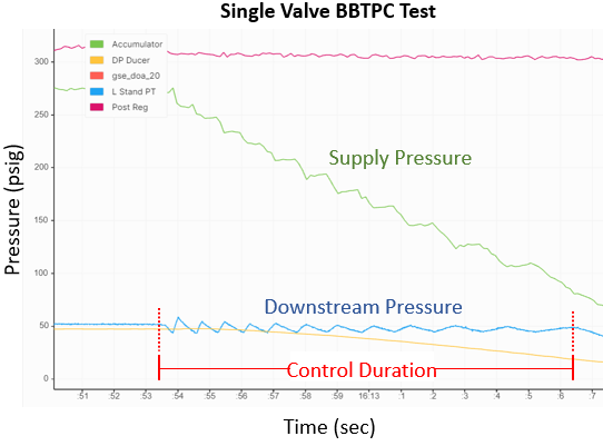
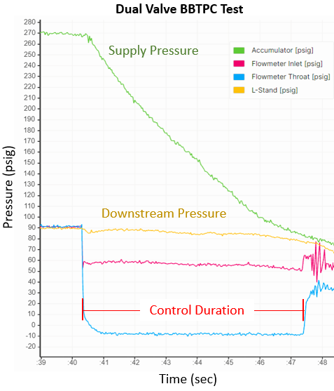
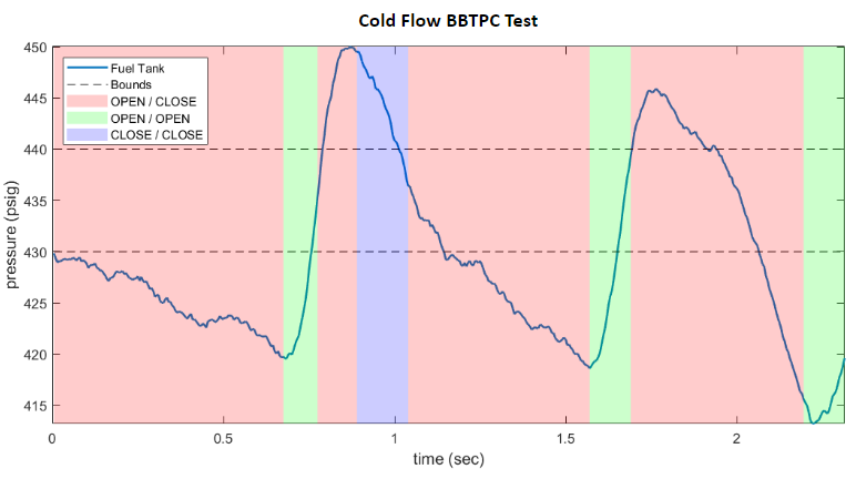
In preliminary testing, the system worked as anticipated for both single and dual valve configurations (shown right). During the full-scale integrated cold flow test (shown below) however, large oscillations in the downstream tank pressures were observed. After reviewing the data, we arrived at the following conclusions:
Time lag between signal output and observable change in downstream tank pressure was nearly twice what was seen in preliminary tests.
Flow coefficient when time periods with one valve open was roughly 2.5 times what we expected.
how it could be improved
Given the above observations from the integrated cold flow test, there are a number of potential ways in which this system could be improved upon for the next iteration:
Optimize pressure transducer placement in the fuel tank to ensure minimal deviation of the pressure measurement from the mean tank pressure.
Characterize valve flow curve across full range pressure drops representative of operational conditions.
Optimize signal smoothing window with respect to measurement latency.
Incorporate system hysteresis resulting form flow friction and compressibility effects into thermal/fluid model.
top skills utilized
cad (Siemens nx/teamcenter)
FEA (Ansys)
fluid system Design
manufacturing
High pressure testing
Thermal/Fluid modeling
FEA (ANSYS)
technical details
The pintle injector for the kerolox rocket engine ME-5 designed by MASA is pressure-fed RP-1 and LOX from independent propellant tanks which must be sustained within a narrow margin of +/- 10 psi of operational pressures (~500 psi). This is accomplished using two separate Tank Pressure Control (TPC) systems, which are each placed immediately upstream of the propellant tanks and are both fed from a single volume of gaseous nitrogen initially pressurized to ~3700 psi. Thus the system requirements are:
TPC shall be pressure-fed from a 26.6L COPV initially pressurized to 3700 psi
TPC shall control downstream propellant tank pressures within +/- 10 psi of operational set points (~500 psi)
TPC shall be successfully demonstrated on both fuel and LOX systems before Summer 2024 hotfire
The simplest TPC solution for this system involves pressure-reducing regulators, however regulator-based TPC (reg-TPC) was found to have certain limitations that may require a more robust system, such as:
The potential inability of spring-loaded single-stage regulators to compensate for supply pressure effect and droop as the upstream pressure decreases and flow rate increases
Large weight and size of dome-loaded regulators which may be able to compensate for aforementioned supply pressure effect and droop
For these reasons, MASA chose to dual-path the design of a separate and potentially more robust TPC system in parallel with reg-TPC that would be based on bang-bang control, referred to as Bang-Bang TPC (BBTPC), where BBTPC would be the first-line system being designed for use in the launch vehicle and reg-TPC would be a backup alternative in the event that BBTPC could not be realized prior to hot fire.
task breakdown
The design of BBTPC was broken in two sub-projects:
Development of a thermo-fluids model sufficient for system sizing
System hardware design, fabrication, and integration
The thermo-fluids model was coded and developed by another engineer, whilst I was the Responsible Engineer (RE) for all system hardware, including:
Fluid manifold design and analysis
System fabrication and integration with Ground Station Equipment (GSE)
Valve and hardware sourcing, management of engineering BOM
It should be noted that while I was not directly involved with the development of the thermo-fluids model, I was in regular communication with the primary RE and I am familiar with the working principles as well as the implementation.
design rationale
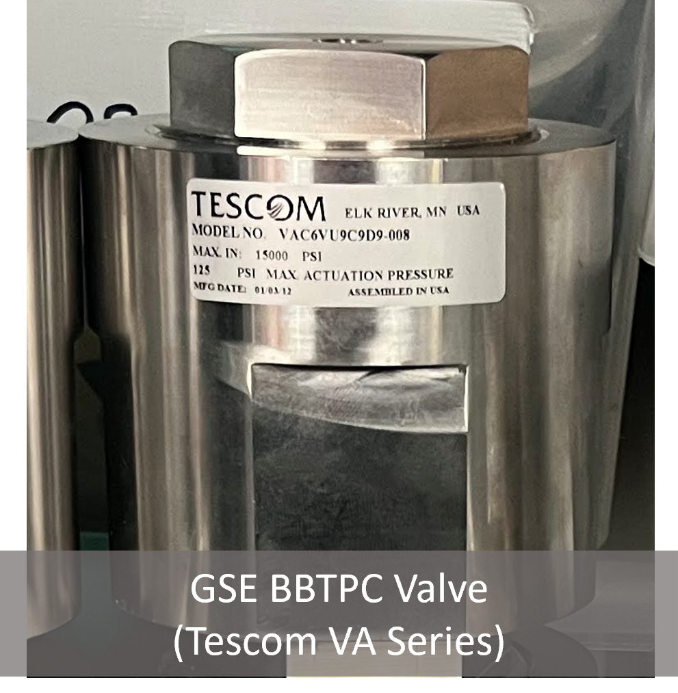
First, the appropriate valve for the system needed to be selected. Initially, it was determined that a cartridge-style Tescom valve would be the best option for the flight BBTPC since it would allow for a great reduction in both mass and volume of the system. This system was limited by the ~55 week lead time of the cartridge-style valve, and so an alternate design using cheaper full-size Tescoms with faster lead times was designed to allow for system testing using hardware that would produce similar results in the interim period. Ultimately, the cartridge-style design would be discarded as the thermo-fluids model was not sufficiently refined in time for the order of the valves to be placed in time for them to arrive before the launch of Limelight. Nevertheless, the cartridge-style manifold design is described herein as it is seemingly the only practical means of realizing BBTPC on a collegiate rocket. That is, the manifold assembly for full-size valves is too large and heavy to be a practical alternative to simpler tank pressure control systems, such as the regulator-based TPC. That being said, the cartridge-style manifold, although never physically realized, would be far more practical, and should be considered in future systems. Second, the manifold designs are separately described. Lastly, the physical assembly for the Fuel BBTPC system that is tested during the 2024 engine coldflow campaign is described.
Control Valve Selection
(Base Model)
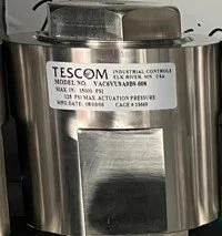
Tescom VA Series
Tescom VA Series
(Cartridge Style)
Pilot-operated: Direct-acting actuation against maximum expected pressure drop and flow rate would require prohibitively large coils and/or current
Normally-closed: TPC should fail closed in the event of power or control loss to prevent propellant tank over pressurization
Cv = 0.75: Higher flow capacity reduces minimum valves required
Actuation time = 50 ms: Faster actuation reduces controller overshoot/undershoot
Cartridge option: Cartridges necessary to meet flight system size requirements, while functional equivalence to the readily available base model allows system development despite excessive lead times
Flight Valve Manifold Design
Component CAD:
System CAD designed in Siemens NX
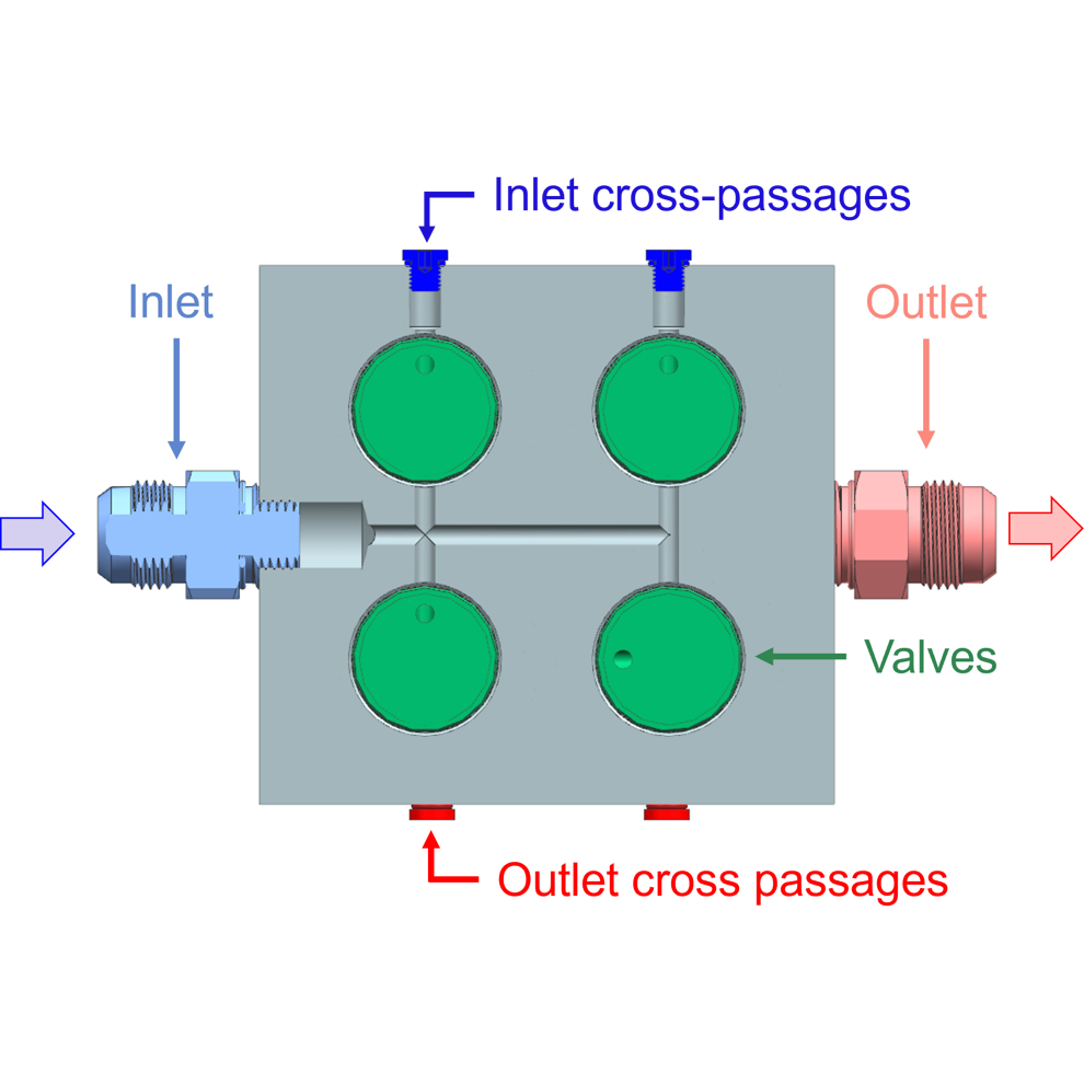
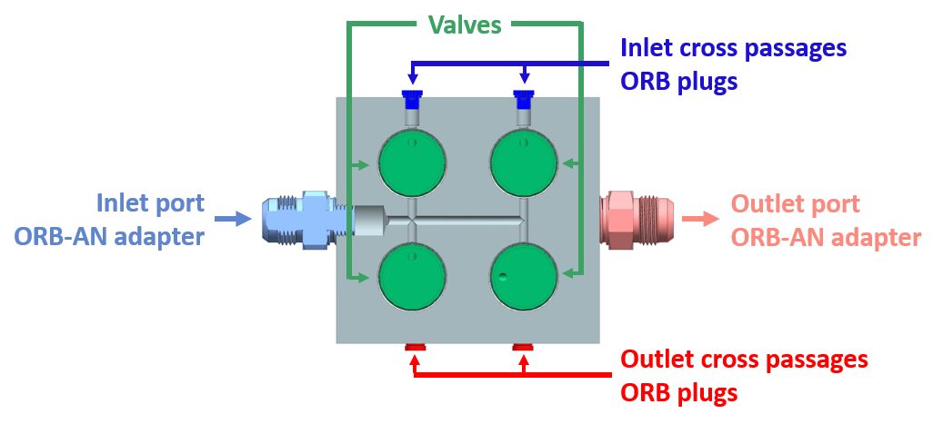
Cartridge-style valves mounted in manifold block reduces system volume by 79% and mass by 39% (relative to the GSE design described below)
Intersecting flow passages made by drilling 2x blind holes into block faces perpendicular to inlet/outlet ports, then tapping the holes for ORB plug fittings
Component FEA:
Static structural analysis completed using ANSYS
Maximum Von Mises stress from simulation compared to material yield/ultimate tensile strengths
Component safety factor evaluated using NASA standard for pressurized systems
AISI 304 SS simulation results:
Yield safety factor: 1.63
Ultimate safety factor: 1.84
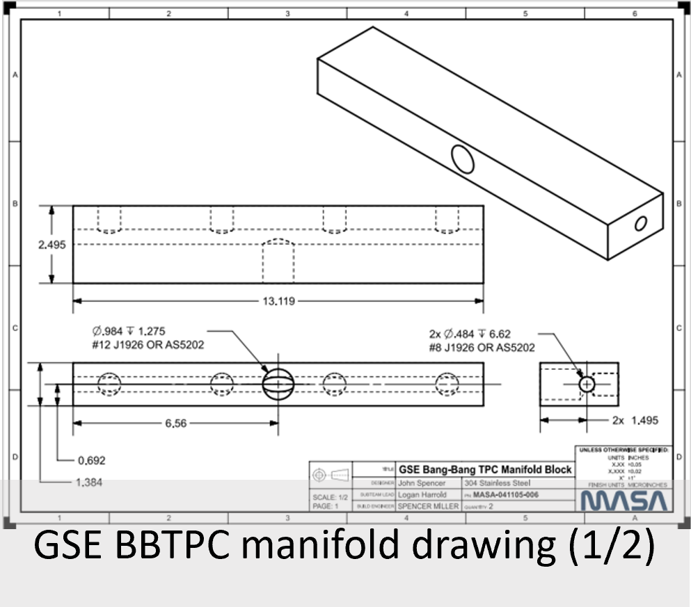
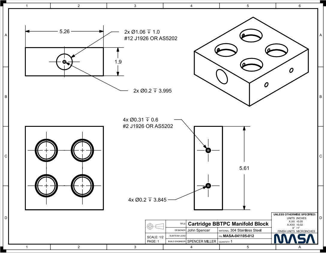
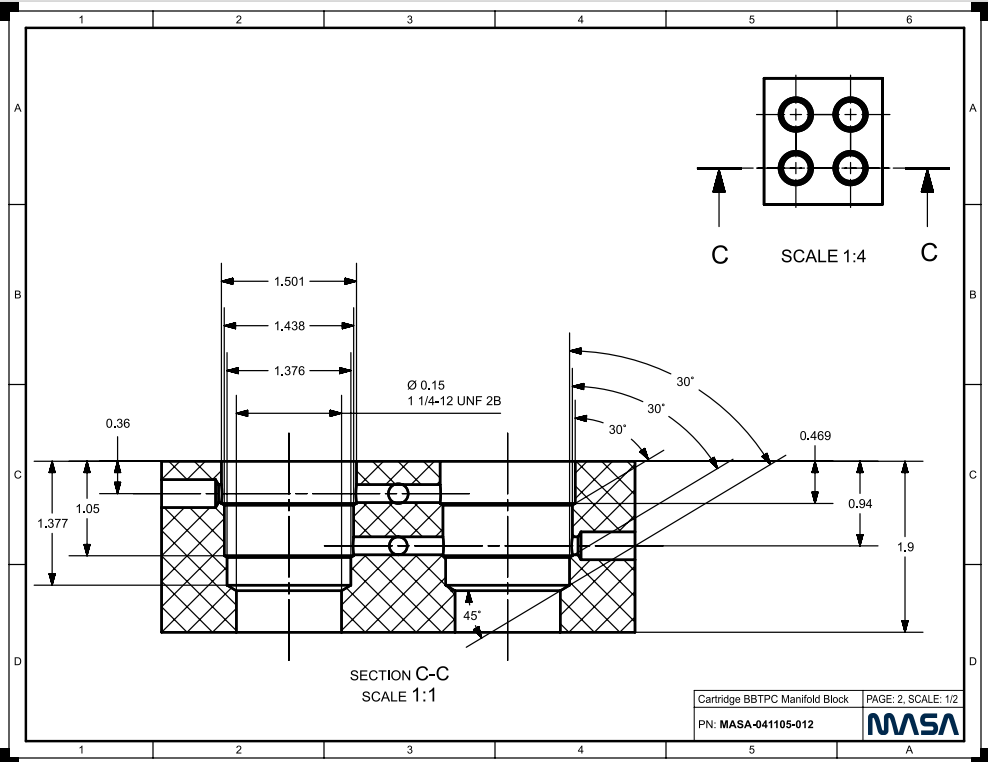
Component Drawings:
GSE Valve Manifold Design
Component CAD:
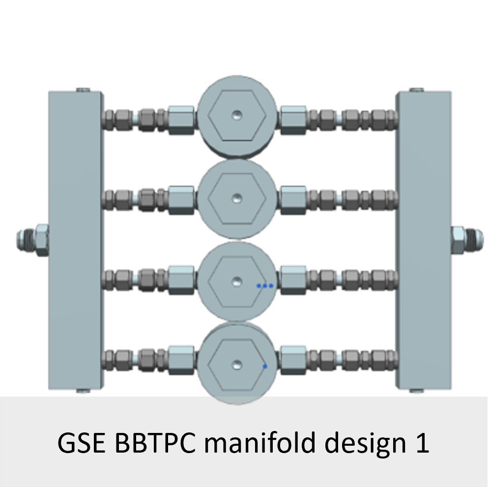
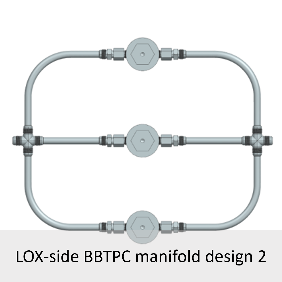
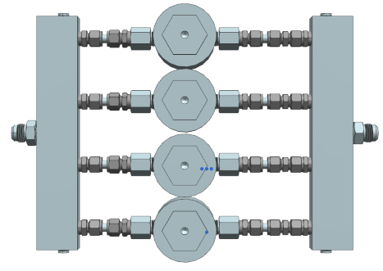
Initial predictions from tank fluid blowdown model required 3 valves on fuel BBTPC and 4 on LOX BBTPC for full duration control
Only C&T MP to NPT fittings available for Tescom ports
Initially believed NPT would not allow for assembly of parallel lines constrained at both ends
Short tubes segments between swage fittings would be used to correct for miaslignment
Problem: manifold blocks too wide to manufacture in house
Blocks replaced with -12 AN tees/elbows
Limited Tescom supply and time constraints required ordering valves of various port sizes, raising concern that flow may distribute unevenly between parallel paths
Swage orificed unions added upstream of valves so that they can be easily swapped during testing to allow quick successive evaluation of various flowpath configuration
Problem: fittings are expensive, and would require flaring several additional segments of thick-walled tubes
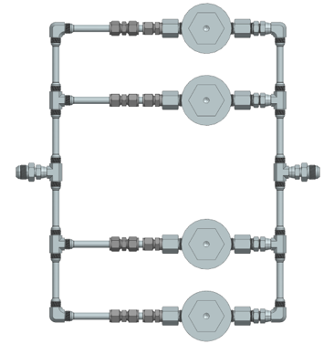
Excess AN fittings replaced with continuous tubes, allowing reduction in both cost and complexity of the assembly
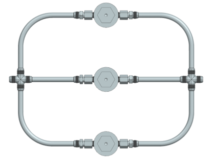
Refinement of tank fluid blowdown model and reassuring results from single valve control test permitted removal of swage orificed unions and one of the valves from the LOX BBTPC assembly
System Fabrication for Coldflow Testing
Fuel-side Manifold:
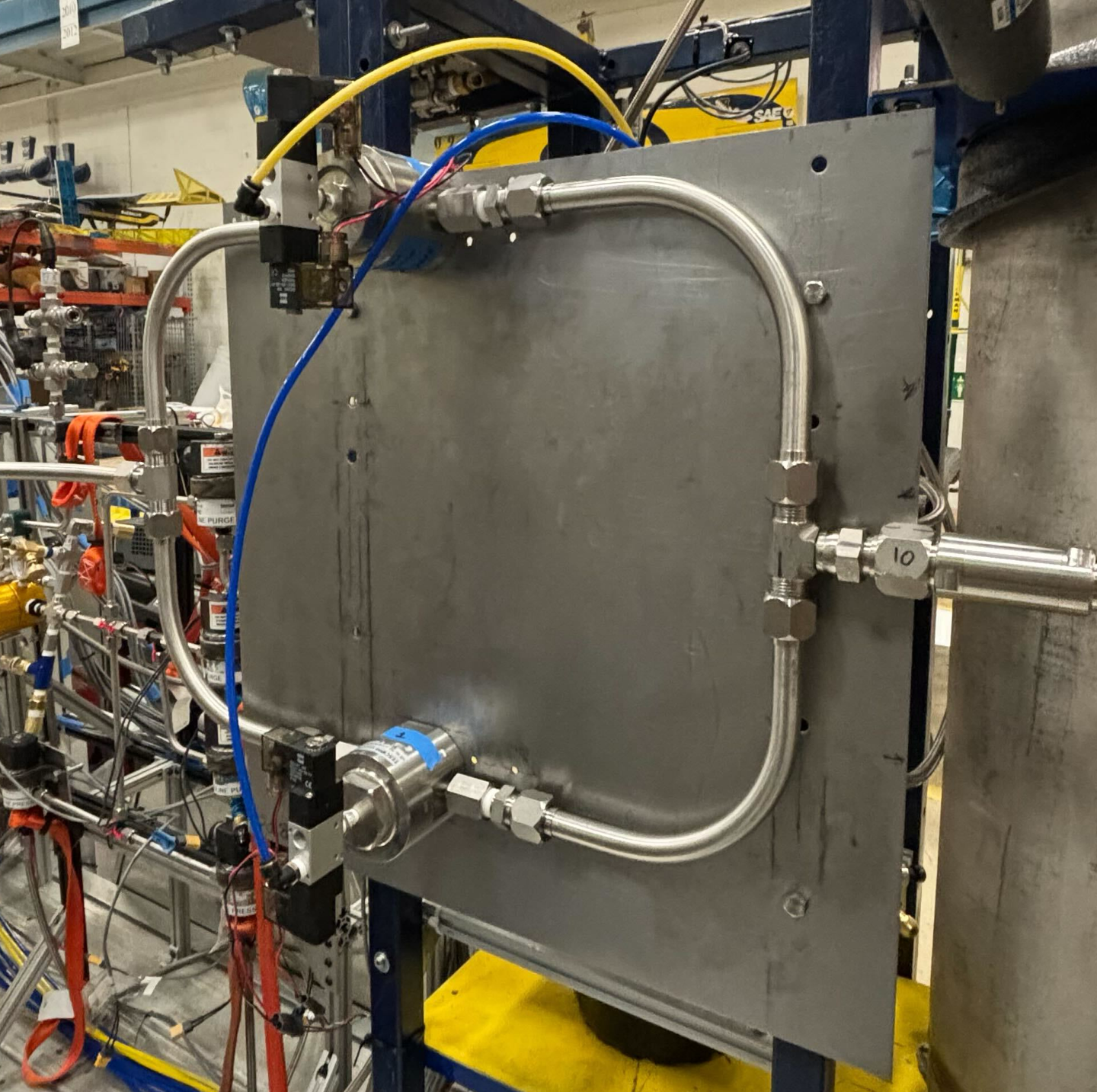
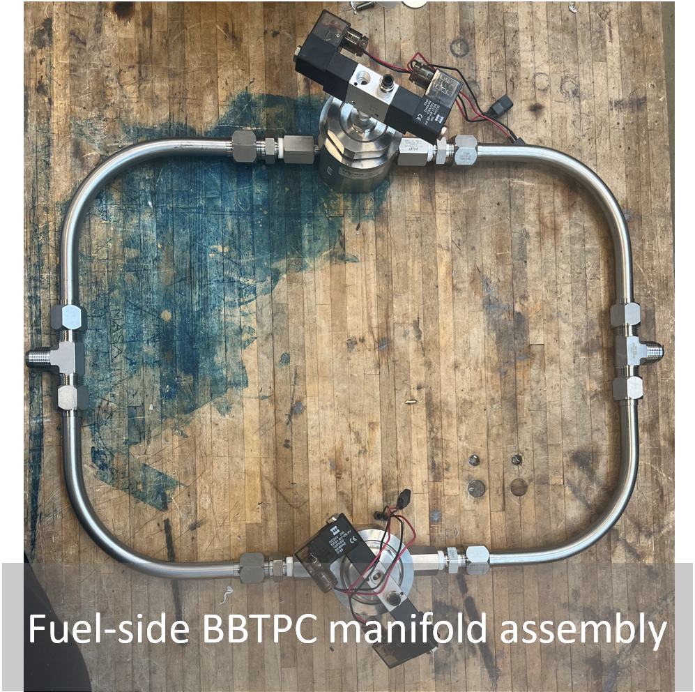
Fuel TPC system assembled by bending + flaring thick wall tube and fabricating the assembly by hand.
Tubes used were 0.083” thick -12 304 stainless steel ordered from McMaster
Thickness is minimum required to support 3700 psi COPV MAWP for system coldflow testing
Fittings:
2x AN tees
4x AN to NPT adapters
4x NPT to MP adapters
GSE Panel Mount:
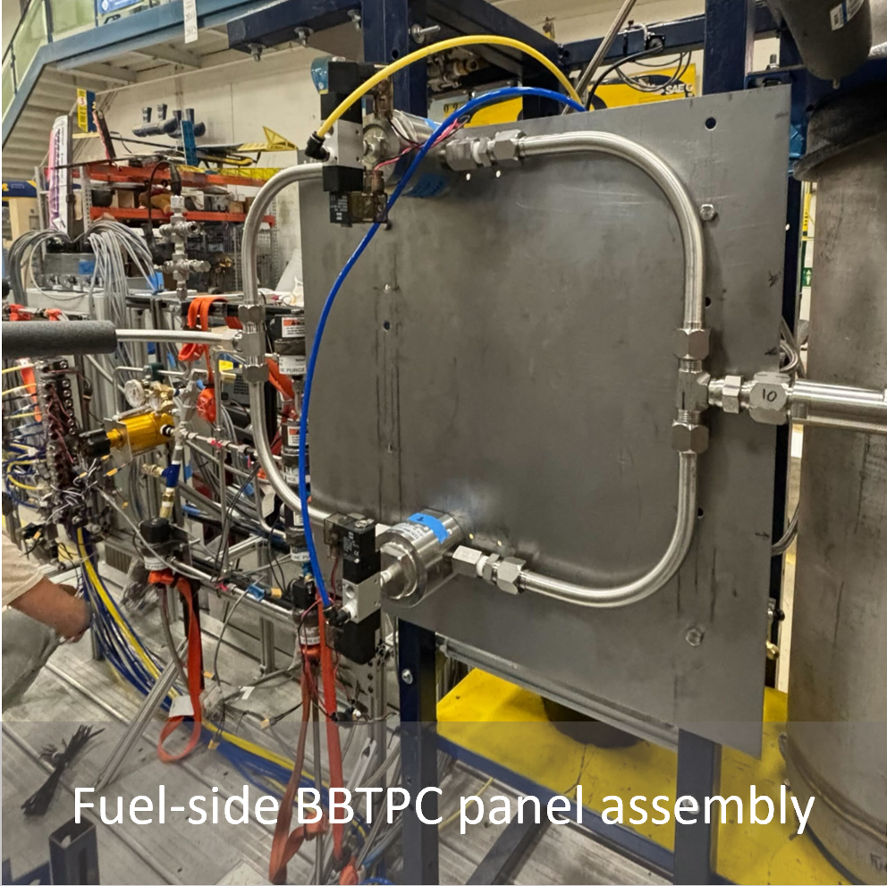
Panel mount sized and machined to allow simple integration and removal of TPC with Ground Station Equipment (GSE) trailer (shown on right).
Sheet used to mount assembly onto GSE was 2’ x 2’ sheet of 14 gauge carbon steel
Tescom valves mounted directly to plate via 4x 10-32 x 3/8 screws
Plate mounted to GSE support beams via 4x 3/8-16 bolts
All holes made using punch & die
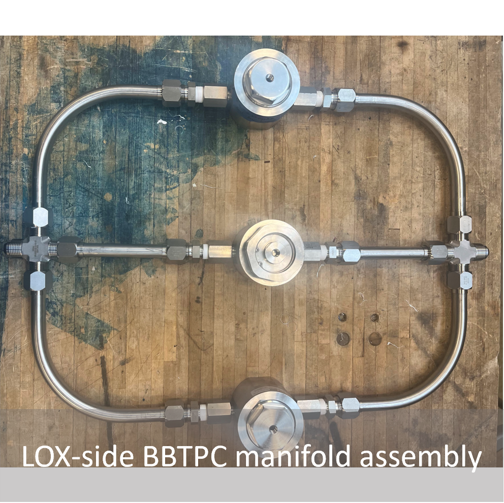
LOX-side Manifold:
Tube selection rationale same as for fuel system
Fittings:
2x AN crosses
6x AN to NPT adapters
6x NPT to MP adapters
Project descoped shortly after assembly due to problem’s with the fuel TPC system during testing
GSE Trailer:
GSE system designed by MASA’s ATLO (Assembly Launch and Test Operations) team
Includes all plumbing subsystems and avionics interfacing electronics and hardware required for propulsion system testing:
Insulated cryogenic tanks (LOX for hotfire, LN2 substituted for coldflows)
Fuel tanks (RP-1 for hotfire, water substituted for coldflows)
COPV’s for tank pressurization, pneumatics, and purge (pressurized with GN2)
Trailer configuration allows convenient transportation to and from both coldflow and hotfire testing sites
